Composite Beam Design Using Nailed Shear Connectors
From its first recorded use over a 150 years ago to now, steel has given rise to some truly outstanding modern civil and building structures. In an typical steel-framed construction, the majority of structural components are beams and columns and usually arranged in an orthogonal layout that aims to maximise the span between columns. However, the foundation and floor slabs still are comprised of concrete, with slabs commonly using concrete poured on top of a trapezoidal metal deck that acts as tension reinforcement for the concrete.

Structurally, the union of these two materials for composite floor slabs enables a highly efficient and lightweight design, which in turn, enables use of thinner slabs, larger clear spans between columns while keeping deflection caused by live loads low, and reduced forces being transferred to the foundations. The knock-on architectural effect is a larger floor-to-floor height that can incorporate buildings services with greater ease and the cost of running these services, if planned with the right strategies. Another advantage relates to the speed and ease of construction, which is undoubtedly faster than a traditional reinforced concrete structure, allowing shorter turnaround time. Here, the metal deck is used as permanent formwork for the concrete slab and it is preferred by most contractors to be “unpropped”, which needs additional checks for loads and deflections at the serviceability limit state during the construction stage. “Propping” relates to the provision of temporary supports to the steelwork and has the benefit of resulting in a greater part of the loading being applied to the (stiffer & stronger) composite section – be it beam or slab – and less to the steel element alone. This enables greater spans to be achieved and can reduce the dead load deflections for long-span beams. Propping may enable secondary beams to be more widely spaced and, thus, reducing steelwork costs. The disadvantage is that the construction process may be adversely affected.
Composite Beam Action & Shear Connection
To ensure this system works as intended, the slab must transfer all its loads to the supporting beam and this is achieved by using shear connectors to create a uniform composite beam action. These connectors are fixed – by either welding or nailing – on top of the upper flange of the steel beam, thus sandwiching the trapezoidal metal deck between the concrete and the beam. Regardless of the connector used, engineers focus on ensuring a sufficient level of shear resistance in the composite system – often termed as “degree of shear connection”.
Composite beams function by tying together the concrete flange with the steel beam and without shear connectors, the flange simply slips over steel as it deflects under any form of loading. The degree of shear connection ranges from “none” to “partial” to “full”, where “none” implies no composite action (concrete and steel behave independently, resulting in slip) and “full” implying a complete transfer of the longitudinal shear up to the plastic design limit (concrete and steel behave as one, assuming an infinitely stiff shear connection). There must be a certain level of stiffness in the connection to prevent this slip, which leads to the term “partial shear connection”. To put it in simple terms, there must be enough shear connectors to limit this slip to a manageable level. In most design standards, however, the stiffness of the connector is implicitly checked by calculating the resistance of the connectors, rather than the stiffness itself.

Partial

Full
In AS/NZS 2327:2017 (amd 2020), two equations define the resistance of the connection in a solid concrete slab: one considers the strength of the steel shear connector; the other considers the strength of the surrounding concrete; and the lower of the two values governs the number of connectors used. Since profiled trapezoidal decks are commonly used, there is reduction factor applied to the solid slab (concrete) value, influenced by the connector and deck geometry.


As the two cross-sections above illustrate, there is a reduction in the volume of concrete caused by the voids in the trapezoidal deck, resulting in most of the volume moving to the top of the connector, and therefore resulting in a reduced capacity compared to a solid slab.
The “ductility” of the connection is defined by the “slip capacity” and must be at least 6.6 mm (AS/NZS 2327:2017, p.246) for the connection to be considered.
Types of Shear Connectors and their advantages
Welded Shear Connectors / studs
Shear connectors are central to this connection detail and, as such, come in two variants: welded and non-welded. Historically, the former is the most common type of shear connector used in composite beams and comes in the shape of a 19mm diameter and 100-125mm long headed stud installed by welding either to the beam through the deck or welded directly to beam on- or off-site, with the deck being perforated to allow the deck to be slotted into the holes. The success of the welded shear connector (or stud), particularly the 19mm diameter, rests in the easily available ferrules and the fact that these connectors exhibit the requisite ductile behaviour and have good resistance to horizontal shear – resisted by the shank – and vertical uplift – prevented by the head.
The crux of the connection rests on the execution of the work of which the weld quality is of primary concern and requires the following:
- Skilled & certified welder;
- Equipment, such as a generator, and numerous electric cables;
- Weld quality depends on the surface conditions of the beam and deck, which require dry surfaces free of scales, rust, moisture, paint or other barriers; and
- Quality control of the weld relies on visual inspection, the sound produced by hammering the stud, and ensuring that a specific angle is achieved during the bending test.
Although this method of installation has been used for decades, welding comes with its own challenges, which often leads to engineers over-specifying the number of connectors required and, therefore, a very conservative design. In relation to the aforementioned points, there are some practical limitations that the structural engineer should recognise when specifying through-deck welding:
- The higher inherent costs associated with skilled personnel and – equally important – equipment needs related to generators to produce enough power for the weld and the use of high-in-demand cranes to hoist the generator into position, not to mention the transportation costs and effort.
- Typically, a generator can only produce power for one welder to operate at any given time.
- Numerous tripping hazards onsite due to the cables.
- Welding quality largely depends on the conditions of the beam surface and whether it is free from moisture, rust, debris, or any other potential barrier to ensure a successful weld.
- Inability to weld on galvanised beams or those coated with intumescent paint for fire protection without the need to conduct finishing works.
- Inaccessibility of the welding equipment in confined areas
- Areas where welding and other “hot work” is not allowed
- Quality inspection tests of welds are subjective and time-consuming
Hilti X-HVB Nailed Shear Connector
To overcome these practical limitations, there are other forms of shear connectors available, such as angles welded to the top flange such as those seen for composite columns but most lack a practical application in composite beams. The one exception is the shot-fired or nailed shear connectors, that do not require welding and therefore have none of the associated limitations.

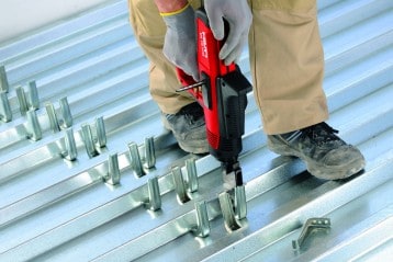
The Hilti X-HVB is one such example of a versatile, L-shaped, nailed shear connector fastened to a beam with two fastener pins driven by a power-actuated tool. While meeting (and comfortably exceeding) the ductility requirements (δuk ≥ 6.6 mm) stipulated in AS/NZS 2327:2017 (amd 2020), this nailed shear connector has its own separate European Assessment Document (EAD 200033) that extends the EC4 Annex B push test requirements to account for the unique characteristics of power-actuated fasteners. Available for over three decades, the X-HVB provides a practical alternative to welded studs and features a simple yet inexpensive installation and inspection procedure that allows consistent fastening quality over multiple fastenings independent of site or weather conditions, with galvanised and painted beams or the presence of rust or moisture not hindering its performance. In fact, none of the aforementioned practical limitations associated with welding apply to the X-HVB.
The connector is available in different heights, making it applicable in a wide range of concrete thicknesses as well as the different heights of the composite deck. Additionally, while it can be installed in flat or profiled trapezoidal deck, the system needs no external electric power source, with the force required to connect the deck with the beam stemming solely from the Hilti DX 76 powder-actuated tool and cartridges. As such, the design resistance is based on the values provided in the system’s European Technical Assessment document (or ETA), granted after successful assessment to EAD 200033.

The installation and inspection can be undertaken reliably and securely by workers after simple training, with an inspection card included in the system kit. The pins are installed correctly when within the 8.2 to 9.8mm range, indicating the minimum and maximum limits. This is a simple “yes” or “no” check and does not rely on any separate visual or aural inspection and greatly hastens the inspection procedure.
As a summary, the X-HVB nailed shear connector system is based on providing a practical alternative to welding and supports a productive construction site through faster installation and inspection. Moreover, the system has synergy with shear connectors welded to primary beams in an offsite location to minimise the onsite limitations; here, the X-HVB connector is ideal for the multiple secondary beams, which typically do not arrive at the site with the studs pre-welded.
The newly released Hilti Shear Connector Design software makes designing composite beams with the X-HVB system simple and efficient.
You can get access to the free software by clicking here
or reach out to our technical support team to discuss your application requirements in more detail!
